|
2
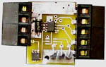
Channel A-D (OWAD2)
Description:
This 1-wire card uses the DS2438
IC to provide four separate functions. The first function is
temperature measurement. The second function uses an A-D channel
to measure the +5V used to power the DS2438 1-wire device. The
third function is one single ended A-D input in the range of
0 to +10.23 volts. The fourth function is a differential A-D
input in the range of +/-250mV.
Differential
A-D Channel:
Connect the A-D channel 2 + input
to common. Now connect your sensor low, negative or common side
to A-D channel 2 -. You may add a low pass filter to this negative
pin by adding up to a 100K ohm resistor in series with your
sensor common lead and connecting a 1.0uF capacitor between
channel 2 - and Common to complete the low pass filter. Connect
your sensor high, positive or "signal" lead to A-D channel 2
+. Since the + side is connected to the 1-wire common your sensor
must be "floating".
Card Type: 3
Connector CN2
(5-pin style) Pinout:
| Pin Numbers |
Description |
| 1 |
Common |
| 2 |
A-D channel 2 + (Connect
to Common) |
| 3 |
A-D channel 2 - (-249.96
to +249.71mV) |
| 4 |
A-D channel 1 (0 to 10.23V) |
| 5 |
+5V Power Output |
Connector CN2
(6-pin style) Pinout:
| Pin Numbers |
Description |
| 1 |
Common |
| 2 |
A-D channel 1 (0 to 10.23V) |
| 3 |
A-D channel 2 - (-249.96
to +249.71mV) |
| 4 |
A-D channel 2 + (Connect
to Common) |
| 5 |
No Connection |
| 6 |
+5V Power Output |
OWconfig:
The "Type" must be 3 as described
above. The "Mode" must always be "Separate power".
Modbus Register
Information:
This device has four consecutive
Modbus input registers on the ICONIO board, one for each function
described above.
| Modbus Register |
Modbus Range |
Conversion |
Description |
| 1 |
0-5760 |
F=0.05625*R1-67
C=0.03125*R1-55 |
Temperature |
| 2 |
0-1023 |
V1=R2/100 |
Power Supply Value |
| 3 |
0-1023 |
V2=R3/100 |
A-D Channel 1 (0 to 10.23V) |
| 4 |
0-2047 |
V3=R4*0.2441-249.96 |
A-D Channel 2 (-249.96 to
249.71 mV) |
Specifications:
| Parameter |
Specification |
| Temperature |
-40 to +85C (-40 to +185F) |
| Temperature Accuracy |
+/-2.0C |
| Temperature Resolution |
0.03125C (0.05625F) |
| Input Impedance |
1.0M ohm Typical |
| Power |
0.5 mA |
| A-D Resolution (Both Channels) |
10 Bits |
| A-D Accuracy (Both Channels) |
8 Bits |
| A-D Channel 1 Range at Rated
Accuracy |
1.50 to 10.23V |
| A-D Channel 1 Over Range
Warning |
A voltage input greater than
10.23V will cause a reading of 0. |
| A-D Channel 2 Over Range
Warning |
A voltage input greater than
249.71 mV will cause a reading of -249.96mV. |
Schematic
and Parts List:
| Reference |
Part Number |
| CN1 |
Digikey 281-1451-ND |
| CN2 |
Digikey 281-1452-ND |
| D1 |
Dallas Semi DS9503P |
| D2-D3 |
Digikey SA5V0ADICT-ND |
| D4 |
Digikey SA10ADICT-ND |
| U1 |
Dallas Semi DS2438A |
|