ICON
I/O Overview
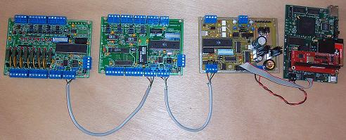
Introduction
The ICON controller connects to a Power/Bus
module for power and to convert the controller's RS232 interface to
Modbus RS485 interfaces for interfacing Modbus I/O devices. The
Power/Bus module also has a Dallas 1-wire bus interface for
interfacing Dallas 1-wire I/O devices and sensors.
The ICON Modcombo I/O module provides 10
inputs and 8 outputs for interfacing sensors and controlling
devices. Other Modbus devices from other manufacturers that support
the Modbus RTU serial or TCP protocol are supported.
Modcombo Power/Bus Controller
Power/Bus Module
The Power/Bus module accepts an unregulated
input of nine to 24 VDC or VAC and generates regulated +5V for
powering the ICON controller and other Modbus I/O devices. This
module also has two RS485 Modbus interfaces, one isolated and one
non-isolated and one Dallas Semiconductor 1-wire device interface
bus.
There are two configurations for
the Power/Bus module. The first configuration is used in conjunction
with the ICON controller and converts the ICON controller's RS232 interface into two Modbus interfaces, a local non-isolated
RS485 bus for Modbus I/O devices
located next to the controller and
an isolated RS485 Modbus to interface
Modbus devices located up to 4000 feet from the
controller.
The second configuration is designed for
remote locations. In this configuration the Power/Bus module connects to the isolated RS485 Modbus
and converts to a local RS485
Modbus for one or more Modbus
I/O devices located with the remote
Power/Bus module. It also supplies power to these I/O
devices.
The system supports one local Power/Bus module with controller
that can communicate with up to 31 remote Power/Bus modules. Total
cable length is 4000 feet. Up to 254 Modbus I/O devices
can theoretically be connected to this Modbus network. In
reality throughput considerations limit the number to something much less.
Each Power/Bus module also contains
a Dallas Semiconductor 1-wire device bus. This bus can support up to 127, 1-wire devices such
as temperature probes with total bus lengths up to 1000 feet
long. The 1-wire devices are controlled from Modbus registers written to
and read from the Power/Bus module. Therefore, from a
programmer's perspective, the Dallas 1-wire devices look like Modbus devices.
Modcombo I/O module
The Modcombo modules connect to the
non-isolated Modbus from a Power/Bus module. This bus supplies +5V
power to the unit along with the the RS485 Modbus signals. Each
Modcombo board has the following specifications:
-
All 10 inputs can be selected for
digital input
-
The first 8 inputs can be selected for
analog input on a channel by channel basis
-
All 10 input channels can do event
counting, slow speed on channels 1-8 (5HZ max) and high speed
(10KHZ) on channels 9 and 10
-
Inputs 9 and 10 can also measure
frequency
-
All 8 outputs are single pole relays
than can switch up to 30VDC or 110VAC non-inductive loads up to
three amps
Interface
Specifications for all Modbus devices
- Serial RTU Modbus (TCP Modbus is also
supported but its operation is over the ethernet port) Baud rate of 9600 or 19200 switch
selectable
- Parity can be selected for none or odd.
- Unit address of 1 to 255 switch
selectable
- Supports Modbus commands 1, 2, 3, 4, 5,
6, 15 and 16
Last updated
December
5,2012
|