Description:
Last updated: April 22, 2003
Description:
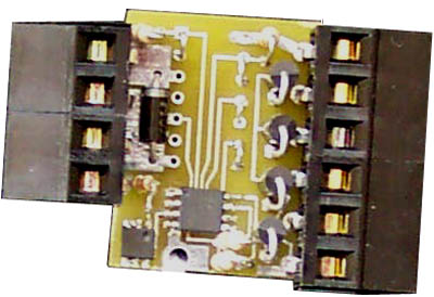
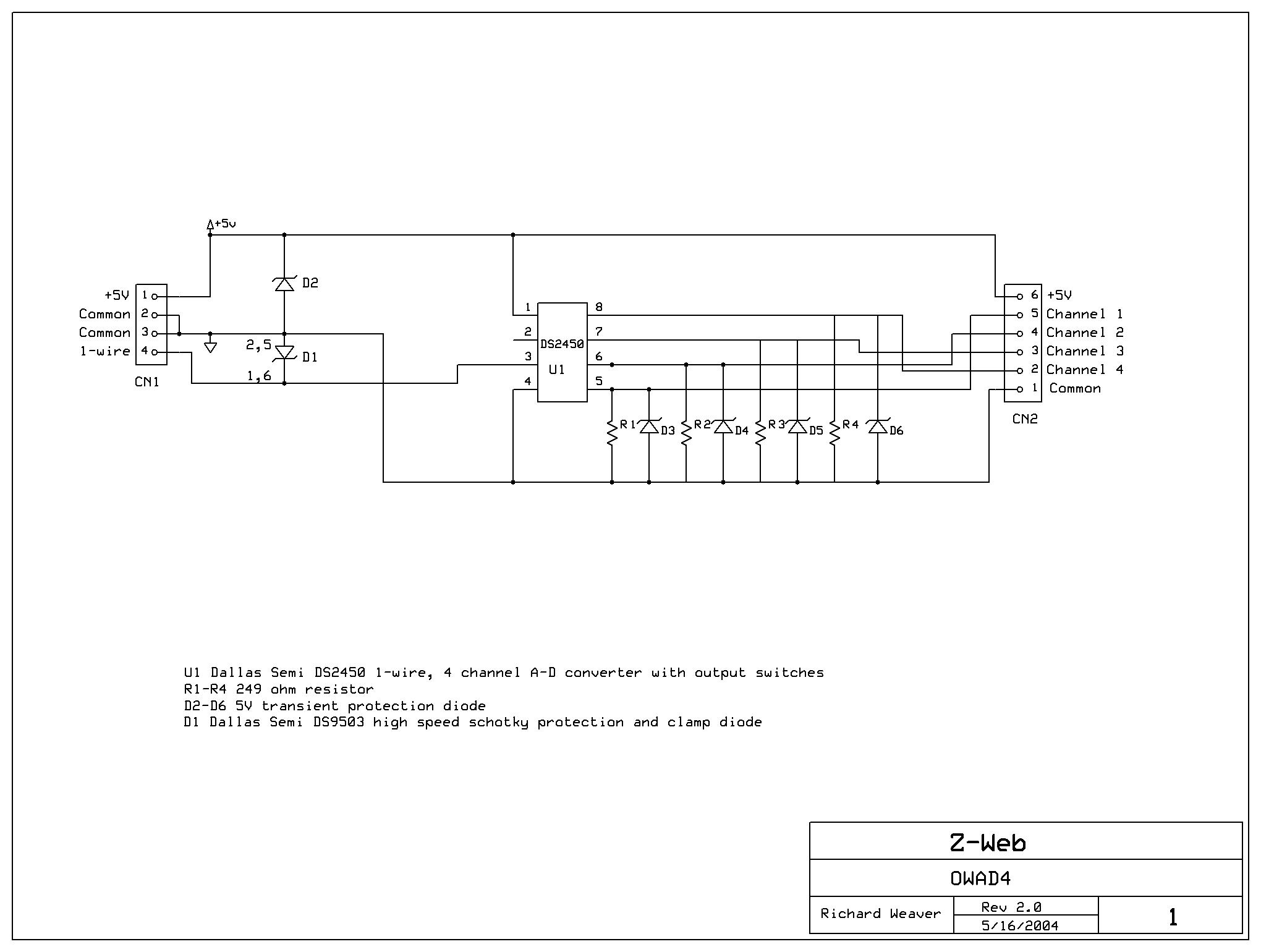
This 1-wire card uses the DS2450 IC in the 0-5.1V A-D input mode to read the state of four digital status inputs. Each channel has a 10K pullup resistor to +5V. It is expected that you connect a dry contact between Common and the desired input channel. It can also be connected to the RELAY4B. This board accepts four optically isolated status input modules. These can be any combination of an IAC5 (senses the presence of 90 to 140VAC) or an IDC5 (senses the presence of 3 to 32VDC).
Card Type: 1
| Type | Description |
| 1 | Selects Input Range 0-5.10V |
Connector CN2 Pinout:
| Pin Numbers | Description |
| 1 | Common |
| 2 | Status channel 4 |
| 3 | Status channel 3 |
| 4 | Status channel 2 |
| 5 | Status channel 1 |
| 6 | +5V Power Output |
OWconfig:
The "Type" must be 1 as described above. The "Mode" must always be "Separate power".
Modbus Register Information:
This device has four consecutive Modbus input registers on the ICONIO board, one for each status channel. Each Modbus register value will be around 1000 when the contact is open and around 0 when the contact is closed. Use the following two ICON expressions to convert from Modbus register value (R) to a 1 or a 0 Status value as follows:
| Modbus Range | Conversion |
| 0-1023 | Status=R/1023 Status=bool(Status) |
Specifications:
| Parameter | Specification |
| Temperature | -40 to +85C (-40 to +185F) |
| Input Impedance | 10K ohm |
| Power | 2.5 mA with all contacts closed. |
Schematic
and Parts List:
| Reference | Part Number |
| CN1 | Digikey 281-1451-ND |
| CN2 | Digikey 281-1452-ND |
| D1 | Dallas Semi DS9503P |
| D2-D6 | Digikey SA5V0ADICT-ND |
| U1 | Dallas Semi DS2450S |